Foundation anchor bolts are cast into the concrete before the steel column base is set. The drawing must fix the bolt group, not just the bolt: thread, projection, bend or anchorage, template and finish all have to agree before concrete is poured.
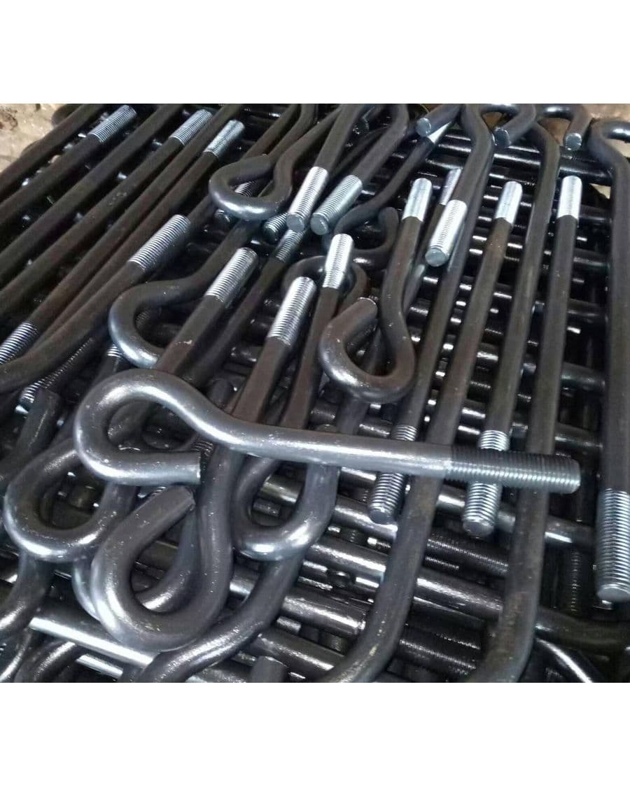
An L-bend and a J-bend are two common anchorage geometries. Neither is automatically better. The structural designer chooses the anchorage detail; the supplier's job is to make the bolt and template to that detail and to state clearly what has been confirmed.
What is the difference between an L-bend and a J-bend?
Both bolts start as a straight threaded shank. The difference is what happens at the embedded end.
| Feature | L-bend | J-bend |
|---|---|---|
| Embedded shape | A single bend, usually about 90 degrees | A hook that turns back towards the shank |
| Setting out | The direction of the leg must be fixed on the drawing | The hook plane, bend radius and tail length must be fixed |
| Concrete cover | Depends on the leg length and its position in the foundation | Depends on the overall hook envelope |
| Normal role | A common anchorage for column bases and equipment | Used where the design calls for a hooked anchorage |
| Main drawing risk | The leg points the wrong way on site | The hook is formed to the wrong radius or plane |
The L-bend is simpler to describe, which is also why it is easy to leave ambiguous. A drawing that shows an L-bend without fixing the direction of the leg can produce a bolt group that is correct in length but impossible to fit to the base plate.
A J-bend has a larger formed envelope. The bend radius and tail length affect how the bolt sits in the reinforcement cage and how much concrete cover is available. The hook cannot simply be bent further on site to make it fit.
Projection is not the same as overall length
One of the most common omissions is the relationship between the base plate, grout or packer, washer, nut and the exposed thread.
The procurement drawing should distinguish between:
- Overall length — from the end of the thread to the end of the embedded leg or hook.
- Projection — the exposed length above the concrete or grout surface.
- Thread length — how much thread is available for the nut and washer.
- Grip or setting-out allowance — the space needed for the base plate, grout, levelling packers and any temporary works.
If the projection is too short, the nut may not engage the full thread. If it is too long, the column may not pack up correctly or the thread may need to be cut on site. Both are avoidable at the drawing stage.
Do not calculate a single universal projection from the bolt diameter. The required projection comes from the base plate detail, grout build-up, nut and washer, and the project engineer's allowance.
What a complete foundation anchor bolt drawing should show
A supplier can only quote and produce against the information received. A useful drawing package normally includes:
- Bolt group reference — a unique mark for each column, base plate or equipment foundation.
- Thread size and pitch — for example M20, M24 or M30, with any non-standard pitch stated.
- Overall length — from thread end to the end of the embedded leg or hook.
- Projection — measured from the finished concrete or grout level, not from the bottom of the excavation.
- Thread length — or the required thread exposure above the nut and washer.
- Bend type and geometry — L or J, leg length, hook tail, bend radius and the plane in which the bend is formed.
- Material and grade — the steel grade required by the design, not a generic “carbon steel”.
- Finish and coating requirement — electroplated zinc, hot-dip galvanizing or another specified system, with the coating standard where applicable.
- Nut, washer and template requirements — whether these are supplied, and whether the template is temporary or remains part of the installation.
- Base plate and grout detail — the bolt spacing, hole diameter and any oversized or slotted holes that affect setting out.
Where the design uses a welded end plate instead of a bend, the same discipline applies: plate size, weld detail, anchor bars and the template pattern all need to be on the drawing.
Why the template matters
A template holds the bolt group at the correct centres while the concrete is placed and compacted. It is not a cosmetic accessory. If the bolts move independently, the base plate holes will not line up when the steel arrives.
The template drawing should show:
- bolt centres in both directions;
- the diagonal check dimensions;
- the orientation mark, so the group cannot be installed 90 or 180 degrees out;
- the projection above the template or concrete;
- how the template is fixed to the formwork or reinforcement;
- whether the template is removed after the pour.
A template made from thin timber can be adequate for a small group, but it can also distort under wet concrete. The material and bracing should match the foundation condition. The project team should decide the method; the supplier needs the dimensions and the required delivered condition.
Choose the finish deliberately
“Galvanized” is not a complete finish specification. Electroplated zinc and hot-dip galvanizing produce different coating thicknesses and behave differently on threads.
For a foundation anchor, the finish should be selected against the exposure condition and the project coating specification. Hot-dip galvanizing is common for exposed or humid sites, but the nut and bolt need to be matched to the coating so the thread still assembles. A heavy coating on an unprepared thread can make the nut difficult to fit.
At Tangtie, electroplated zinc finishing is handled in-house. Hot-dip galvanizing and other processes are coordinated with qualified finishing suppliers; the finish stated in the quotation is the finish to confirm for the batch.
Common mistakes to catch before the concrete pour
- Using a typical detail without the project dimensions. A standard sketch does not fix the base plate, grout thickness or exposure condition.
- Showing the projection but not the overall length. The fabricator cannot derive the embedded leg reliably from a single visible dimension.
- Leaving the L-leg direction undefined. The bend may be correct but point into the wrong part of the foundation.
- Changing the bend on site. Field bending can crack the coating, alter the anchorage geometry and invalidate the approved detail.
- Ordering the bolts without the template. The individual bolts can be right and the group still be wrong.
- Writing “galvanized” without a coating requirement. The finish may pass visually and still fail the project specification.
- Mixing coated and uncoated nuts. The assembly must be checked as a set, not as separate parts.
What to send with an RFQ
For a foundation anchor bolt quotation, send:
- the foundation or base plate drawing, including revisions;
- the bolt schedule by mark;
- thread size, overall length, projection and thread length;
- L/J bend detail or welded anchorage detail;
- material grade and coating specification;
- template requirement and marking method;
- quantity by bolt group, not only total weight;
- required inspection or document package;
- delivery destination and required packing method.
If some information is not yet fixed, mark it as a hold point. A supplier should not guess a projection or bend to make the quotation look complete.
Tangtie supplies foundation anchor bolts and embedded anchor bolts to drawing. Dimensions, material, finish and documentation are confirmed against the approved drawing before production. Load capacity and anchorage design remain the responsibility of the project engineer.
Next step: send the base plate and foundation detail with the bolt schedule. The quotation can then identify the exact dimensions and documents that need confirmation.
This note is general technical guidance prepared for the product library. It is not a project-specific approval and does not replace the specification issued by the project engineer. Values requiring test evidence are not published.